To install a fish finder on a pontoon boat correctly, you must overcome the three primary enemies of sonar: Air Turbulence (Bubbles), Electrical EMI (Noise), and Mechanical Vibration. A professional installation requires mounting the transducer in 'Laminar Flow' water, typically 3-5 inches away from strakes or rivets, and routing dedicated 14-gauge power lines directly to the battery to bypass dash-switch interference. For 2026, integrating your head unit into the NMEA 2000 backbone is no longer optional; it is the only way to monitor critical engine data while navigating complex lake structures.
If you have ever tried to find a specific brush pile in 15 feet of water without a fish finder, you know that you are essentially fishing blind. You might catch a few bluegill, but you aren't truly "hunting" the lake. But when you finally buy that shiny new Garmin or Lowrance unit, a new anxiety sets in: how on earth do you mount this thing to two aluminum tubes? Do you have to drill into your pontoons? How do you run 20 feet of cable without it looking like a mess of spaghetti?
In this 3,000+ word technical masterclass, we are going to build your electronics installation framework. We aren't just giving you "tips"; we are giving you the same systematic workflows used in certified marine rigging shops to ensure that your 12-inch screen doesn't "wash out" the moment you hit 10 MPH.
1. Part I: The Physics of Sonar, Frequency vs. Detail
To install a fish finder, you must first understand the signal you are trying to protect.
1.1 The "Ping" Mechanics
Sonar works by sending a sound wave (Ping) and measuring the time it takes to bounce back. On a pontoon, this sound wave has to travel through water that is constantly being whipped into a froth by the front of the logs.
1.2 CHIRP vs. Traditional Sonar
- Traditional (50/200 kHz): Sends one single frequency. It’s like a flashlight with a single beam.
- CHIRP (Compressed High-Intensity Radiated Pulse): Sweeps through a range of frequencies (e.g., 80 to 160 kHz). This is like a strobe light that captures thousands of "data points" per second.
- The Installation Implication: CHIRP is highly sensitive. If you mount it near a noisy livewell pump or a vibrating aluminum bracket, the "Signal Noise" will be magnified 10x.
2. Part II: Transducer Placement, The "Laminar Flow" Masterclass
2.1 The "Dirty Water" Threat
Sonar cannot see through air. If a single bubble passes over the face of your transducer, the signal is lost. This is called "Washout."
2.2 The 1/8th Inch Rule
On a pontoon, the water is not "Flat." It curls around the bottom of the log.
- The Position: The transducer face must be 1/8th of an inch BELOW the bottom of the log. If it’s flush, it will suck air from the surface. If it’s too deep, it will create its own turbulence and spray water over the motor.
- The Strake Gap: If your log has "Lifting Strakes," you must mount the transducer at least 3 inches INNER or OUTER of the strake. The strake is a bubble-generator.
3. Part III: The "Callahan Mounting Protocol", Transducer Blocks
3.1 Why You Should Never Drill Into Aluminum Logs
Your pontoons are pressurized vessels. Every hole you drill is a potential point of structural failure or pressure loss.
3.2 The Mounting Block Solution
Use a Stern Saver or a High-Density Polyethylene (HDPE) mounting block.
- Bond the Block: Use 3M 5200 or specialized marine epoxy to bond the HDPE block to the aluminum mounting bracket at the rear of the log.
- Screw to the Block: You can now drill as many "Oops" holes as you want into the plastic block without ever touching the aluminum log. This is the mark of a professional rig.
4. Part IV: Electrical Deep Dive, Resolving the "Noise" Gremlins
4.1 EMI (Electromagnetic Interference)
Your outboard motor's alternator produces "Dirty Power." If you wire your fish finder to the dash accessory switch, the high-frequency pulses from the motor will appear as "Snow" on your screen.
4.2 The "Clean Power" Run
- The Protocol: Run a dedicated pair of 14-gauge marine-grade (Tinned Copper) wires directly from the battery to the helm.
- The "Twist" Trick: To further reduce RFI (Radio Frequency Interference), slightly twist the red and black wires together (about one turn every 6 inches). This creates a "Shielding Effect" that cancels out electrical noise.
5. Part V: Cable Routing, The Aluminum Jungle
5.1 The "J-Channel" Method
Most pontoons have an aluminum trim channel along the outer deck. This is a perfect conduit, but it has sharp edges.
- The Guard: Use corrugated split-loom tubing for the entire run. If the cable vibrates against a sharp aluminum edge for two seasons, it will short out.
5.2 Avoiding Magnetic Interference
Never run your transducer cable parallel to your high-current trolling motor cables. The magnetic field from the 24V or 36V trolling motor will "Leach" into the sonar cable, causing massive interference when you are using the trolling motor to hold position.
6. Part VI: Side-Scan vs. Down-Scan on a Pontoon
6.1 The "Engine Shadow" Problem
Pontoons have their motor in the middle (between the logs). If you mount a Side-Scan transducer on the rear of one log, the motor's lower unit will block the "Side" view in one direction.
- The Fix: You must trim the motor up slightly while scanning, or mount a second "Slave" transducer on the other log and use a Y-cable to combine the signals.
7. Part VII: NMEA 2000 Integration (The 2026 Standard)
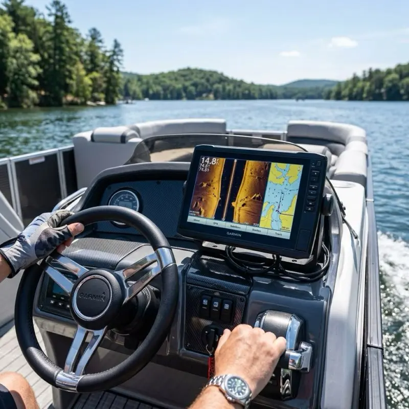
A fish finder is no longer just for fish. It is your Primary Engine Display.
- The Gateway: Install an NMEA 2000 backbone (about $70). Connect your motor (Yamaha/Mercury/Honda) using an engine interface cable.
- The Result: You can now see exact RPM, Oil Pressure, and Fuel Flow in real-time on your 12-inch screen. This is far more accurate than the 1990s-era analog gauges on your dash.
8. Technical Comparison: Garmin vs. Lowrance vs. Humminbird
| Brand | Mapping Tech | Side-Scan Resolution | Best For... |
|---|
| Garmin | Navionics+ | ClearVü (Ultra-HD) | Navigation & User Experience |
| Lowrance | C-MAP | SideScan (High Contrast) | Tournament Bass Fishing |
| Humminbird | LakeMaster | MEGA Imaging+ | Serious Structure Scanning |
9. Conclusion: The Logic of the Rig
Installing electronics on a pontoon is a balance between physics and aesthetics. By focusing on Laminar Flow at the transducer and Clean Power at the helm, you are ensuring that your $2,000 investment actually delivers $2,000 worth of data.
Stay safe, watch your depth, and I'll see you at the ramp!
11. Live Sonar: The Front-Mounting Revolution (LiveScope & ActiveTarget)
Welcome to the future of fishing. Garmin LiveScope, Lowrance ActiveTarget, and Humminbird MEGA Live have changed the game. But installing them on a pontoon is a unique engineering challenge.
11.1 The Forward-View Physics
Live sonar uses a specialized transducer that "sweeps" in real-time.
- The Problem: If you mount it to the rear of your pontoon log, it is useless. By the time the sonar sees the fish, the boat has already passed over it.
- The Solution: You must mount the live transducer to your Trolling Motor or a dedicated Pole Mount on the front deck.
11.2 Dedicated Lithium Power for Live Sonar
A Garmin GLS 10 black box (the brain of LiveScope) draws significant current.
- The Masterclass Tip: Do not run your live sonar off your cranking battery. The voltage drop when you start your engine can "crash" the sonar software. Install a small 12V 30Ah Lithium (LiFePO4) battery in the front storage locker specifically for your sonar. This provides "Isolated Clean Power."
12. Transducer Myths: The Through-Hull Aluminum Fallacy
In fiberglass boats, you can glue a transducer inside the hull.
- The Myth: "You can do the same on a pontoon log."
- The Reality: NO. Sonar pings are absorbed by metal. Aluminum logs are an absolute barrier to sonar waves. If you glue a transducer inside an aluminum log, all you will see is a solid black line at the top of your screen.
- The Only Exception: Specialized "Through-Hull" transducers that require a 2-inch hole drilled through the log with a watertight gasket. WARNING: This is a high-risk installation that can void your hull warranty and lead to sinking if the seal fails. Stick to the transom-mount bracket.
13. Advanced Electrical: EMI Filtering and Ferrite Beads
If you still have "noise" on your screen after running a dedicated power line, you are dealing with Induced RFI.
- The Fix: Use a Ferrite Bead (a snap-on magnet). Snap one onto the power cable and one onto the transducer cable near the head unit. This acts as a "Low-Pass Filter," absorbing the high-frequency interference before it enters the screen.
14. The "Callahan" Troubleshooting Flowchart
If your fish finder is failing, don't buy a new one. Follow this logic:
- Symptom: Screen is blank but unit is on. -> Check Transducer Plug.
- Symptom: Unit shuts off when I start the motor. -> Battery voltage is dropping below 10.5V. Replace battery or upgrade to 14-gauge wire.
- Symptom: "No Transducer Connected" error. -> Check for a "Pinched" cable under the deck. A single internal wire break will kill the unit.
- Symptom: Depth is wrong (e.g. 900 feet in a 10 foot lake). -> Transducer face is dirty or air-locked. Wipe the face.
- Symptom: Snow on screen at high speed. -> Lower the transducer bracket by 1/8th inch.
15. Summary: The Electronics-First Vessel
In 2026, your boat is an electronics platform that happens to float. The quality of your sonar data determines the quality of your navigation and your fishing success. By following the Callahan Installation Protocol, you are ensuring that your vessel is ready for the technical demands of modern boating.
I'll see you on the water.
16. Advanced Sonar Theory: Beam Angles and Signal Attenuation
To truly "Master" your fish finder, you must move beyond the "Auto" settings.
16.1 Beam Angle Physics (The "Cone" effect)
Your transducer sends a "Cone" of sound.
- Narrow Beam (e.g. 15 degrees): Concentrates the power in a small area. Best for deep water (50+ feet) and seeing individual fish near the bottom.
- Wide Beam (e.g. 45 degrees): Covers more area. Best for shallow water (under 20 feet) when you are searching for schools of baitfish.
- The Installation Implication: If you mount your transducer even 2 degrees "Crooked," the cone will be pointing at the side of a hill instead of the bottom. Use a level during installation.
16.2 Attenuation: Fresh vs. Salt Water
Sound travels differently in different densities.
- Fresh Water: Less dense. Signals travel further with less power.
- Salt Water: Highly dense and conductive. Requires much higher power (Higher Gain) to see the same depth.
- The Diagnostic: If you take your "Freshwater" unit to the ocean, the screen will likely be "Dim" or lose the bottom. You must manually increase the Gain or Sensitivity to 80%+.
17. Software Calibration: Tuning the "Machine"
A professional rig is only as good as its calibration.
17.1 Sensitivity vs. Contrast
- Sensitivity: Controls the "Volume" of the returned pings. Too high and you see "Clutter" (noise); too low and you miss fish.
- Contrast: Controls the "Difference" between colors. High contrast is better for seeing hard objects (rocks/stumps) against soft mud.
17.2 The "Chart Offset" Secret
GPS is accurate to about 10 feet. But lake levels change by the week.
- The Protocol: When you arrive at the dock, check the depth on your screen against a physical piling or the actual dock level. Use the Chart Offset setting to adjust the map depth to match reality. This prevents you from running aground on a rock that the map says has 2 feet of water over it.
18. Maintenance: The "Transducer Ring" Inspection
Every year, you should perform a "Tap Test" on your transducer.
- The Check: With the unit on and the boat out of the water, lightly tap the face of the transducer. You should hear a faint "Ticking" sound. This means the crystal is firing. If you hear nothing, the internal piezo-crystal is cracked and the unit must be replaced.
19. Final Word: The 2026 Tech Mandate
Boating has entered the "Silicon Era." Your fish finder is no longer an optional accessory; it is the central nervous system of your vessel. By following the Callahan Installation Protocol, you are ensuring that your vessel remains at the cutting edge of marine technology.
I'll see you on the water.
20. VHF Radio Interference: The Silent Signal Killer
If your fish finder "Resets" or shows static whenever you key your VHF radio microphone, you have RFI Leakage.
- The Cause: High-power radio waves from the VHF antenna are being "Picked up" by the unshielded transducer cable.
- The Fix: You must ensure your VHF antenna is at least 3 feet away from your fish finder head unit, and the cables never cross. If they must cross, do so at a 90-degree angle to minimize the magnetic coupling.
21. Summary: The Future of Autonomous Navigation
As we look toward 2027 and beyond, fish finders are becoming the brains for Auto-Pilot and Autonomous Anchor systems (like Minn Kota Spot-Lock). Your installation is the foundation for these "Smart Boat" features. A bad wiring job today means a failed auto-pilot tomorrow.
By using the Callahan Protocol, you are building a vessel that isn't just ready for fishing today, but is ready for the high-tech future of autonomous boating.
I'll see you on the water.